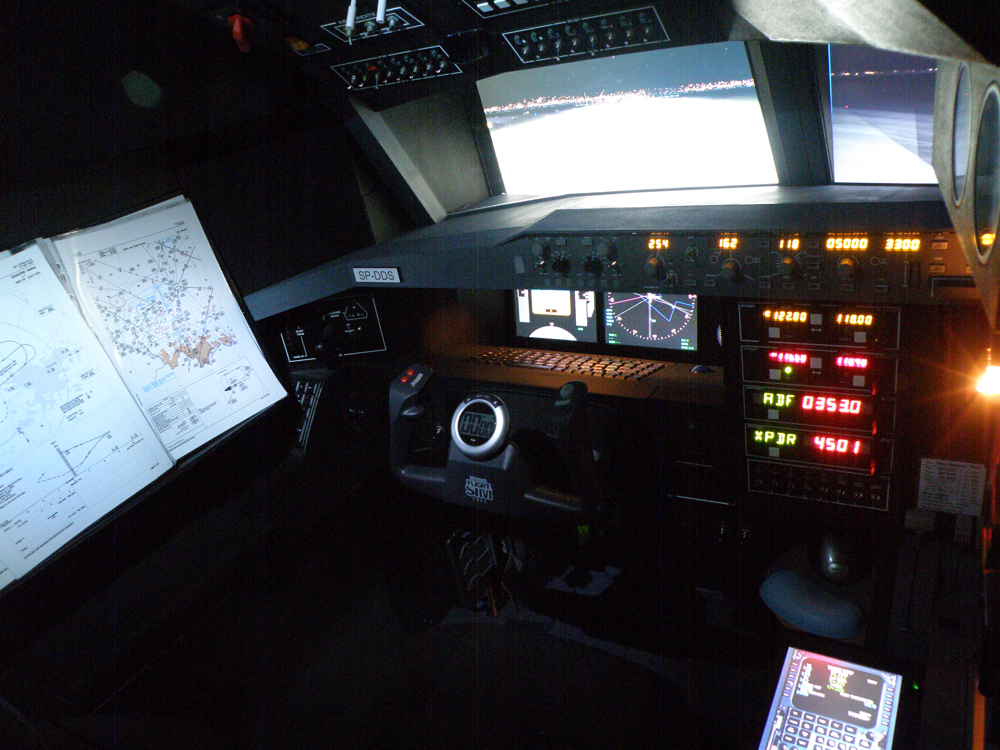
Drzewiecki Design archive

Home Cockpit: History of Build

A preserved account of the two-stage home cockpit project, from its first chipboard walls to the completed dual-computer flight deck.

Built 2005–2009 · operated until 2011
Archive material. This project reflects consumer flight-simulation hardware, software and construction methods used between 2005 and 2011. Period product names and reference context are retained as part of the original record; they are not current recommendations.

Version 1: the original cockpit

Construction began in October 2005. The first complete and fully operational version was presented on 31 December 2007.

October 2005 – December 2007

The beginning

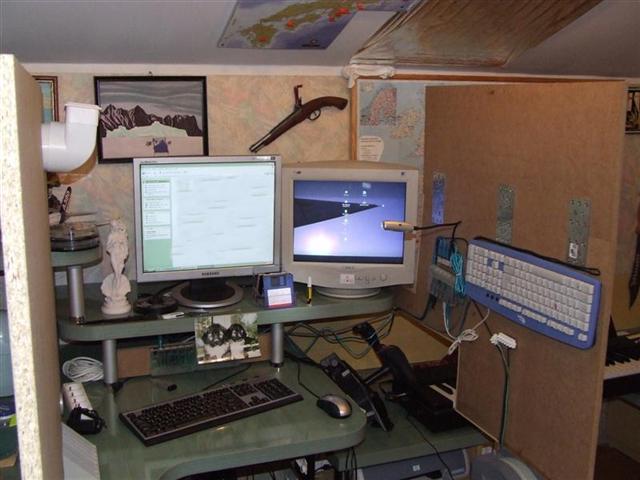
I began by ordering two 16 mm chipboard panels. The 160 cm-high walls provided a large surface for arranging the equipment. On the right wall I installed one of the keyboards and one of six USB hubs.

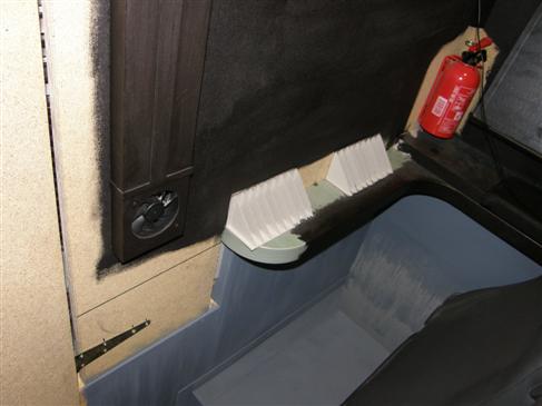
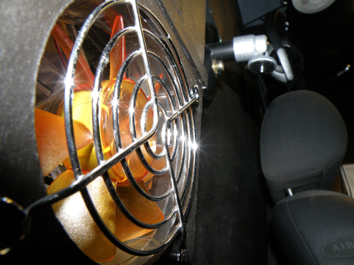
Ventilation had to be considered from the start: the small enclosed cabin and the computer produced enough heat to make air circulation poor. A 230 V fan in the left wall supplied fresh air to the cabin.

The next challenge was the main instrument panel. It needed to coexist with a normal desk, so I initially considered hinges that would allow the complete panel to swing upward after the yoke was removed. Structural and durability problems made that solution impractical.

A second concept placed the panel and yoke on guides so that the assembly could be lifted. This, too, was abandoned. The planned monitor and four GoFlight modules, including the MCP Pro, made the unit too heavy; motorizing it from the cockpit roof was unrealistic.

First chipboard wall of the home cockpit Early main-panel concept Main-panel lifting concept

Throttle and diagnostic panel

With the main panel postponed, I worked on the other controls. The first throttle was built from an old joystick potentiometer and a shaped wooden rolling-pin handle. The mechanism was configured so that pulling the lever fully aft activated reverse thrust. A small bulb illuminated the lever from within, and four lighting switches were installed on the front panel.

I also built a diagnostic panel with three voltmeters, one of them manufactured in 1946. They monitored the 230 V supply, the 7 V lighting circuit and the 7 V computer-side circuit. A clock and a touch-screen handheld computer provided quick access to airport frequencies, runway lengths and elevations during night flights.

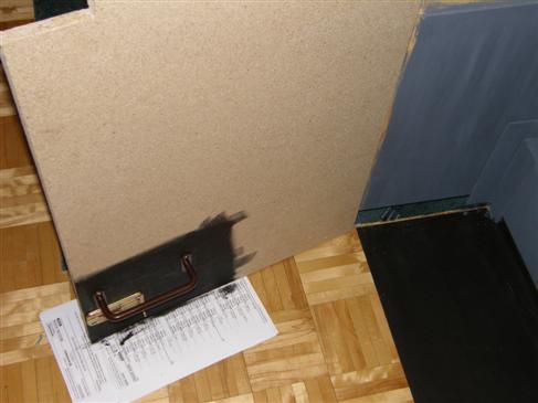
After testing, the components were painted and installed on the right wall. Removable access panels allowed the throttle and electrical wiring to be serviced without dismantling the cabin.

Home-built throttle unit Diagnostic panel with voltmeters Installed controls on the right cockpit wall

Seat and platform

The carpet beneath the cockpit was cut away and replaced with grey floor covering. A used Volkswagen seat bought at an online auction was refurbished, tested and mounted on a painted platform. The platform raised the low seat to the correct height and provided a flat structure for its metal adjustment rails.

Refurbished cockpit seat Seat platform during assembly Seat platform installed in the cabin

Rudder pedals and head tracking

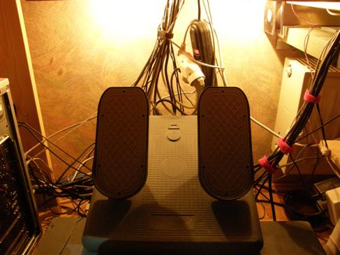
The raised seat platform left no straightforward place for the rudder pedals. I therefore built a rigid frame with two columns and fitted it among the wiring beneath the desk. Mounting the pedals at an angle made the position more realistic and comfortable.

In mid-2006 I added a NaturalPoint TrackIR 4 Pro. The reflective markers were mounted to a headset on a 2 mm cardboard support. Early tracking errors caused by hair interfering with the markers were solved by adding the connector visible in the photograph.

Angled rudder-pedal frame TrackIR reflector mounted to a headset

Computer upgrade and third monitor

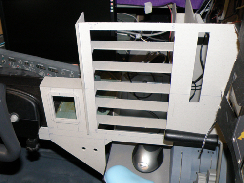
Preparing for Flight Simulator X, I upgraded the computer with an Intel Pentium D 930 3 GHz processor and two synchronized XFX GeForce 6800 graphics cards with 256 MB each. After a short pause in construction, a 15-inch monitor bought during a trip to China was installed in the right side of the panel. It required a dedicated frame and a separate mouse shelf. The two main monitors shared one graphics card, while the third used the second card.

Third monitor fitted to the right panel Monitor frame during construction Third-monitor installation detail

Main panel and secondary controls

To retain use of the room as an office, only the centre section of the panel was made movable. The yoke could retract below the desk and be replaced by a normal keyboard. The centre section ran on guides, and a hood connected it to the two side walls. Openings on the right were prepared for a GoFlight module and a numeric keypad used for online ATC communication. Integrated lighting illuminated the keyboard when the yoke was hidden.

Movable centre panel section Retractable yoke arrangement Main-panel hood under construction Main panel with keyboard position

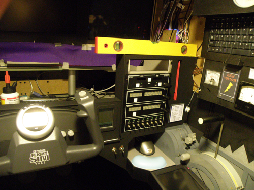
A second module, built from another used joystick, controlled spoilers, mixture and propeller pitch. Two salvaged keyboard keys operated TO/GA and the parking brake. The internally illuminated unit used handles from a CH yoke and was installed near the throttle.

Secondary engine-control module Control module mechanism Illuminated control module Control module installed by the throttle

Roof, acoustics and simulator software

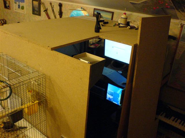
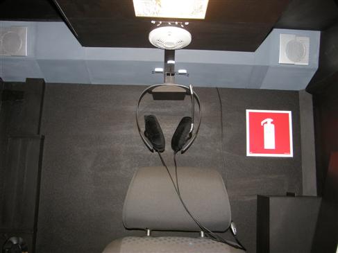
The roof was made from 16 mm chipboard and fixed to the walls with seven screws. It included openings above the door, for the cable bundle and for the network-card antenna. Enclosing the cabin created a distinctive acoustic effect: the timber resonated with low-frequency sound and the entire structure vibrated. It also made thermal management even more important.

After an unsuccessful attempt to move from FS2004 to FSX, I decided that the hardware cost was not justified by the improvement available at the time. Instead, FS2004 was enhanced with Active Sky 6, Ground Environment Pro, FS Global 2008 and the Ultimate Terrain products for the USA, Europe and Eastern Europe.

Cockpit roof under construction

Glass cockpit displays

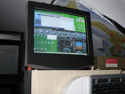
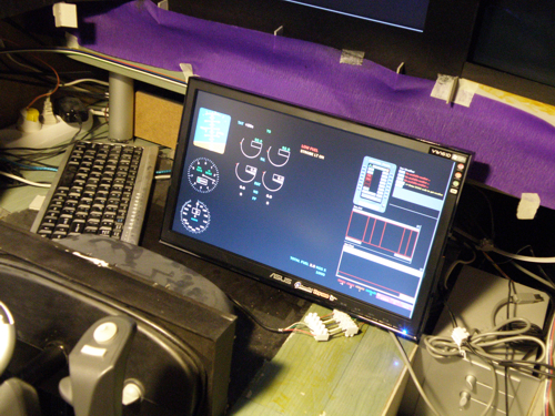
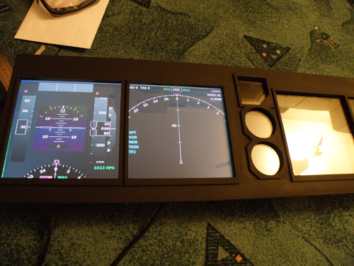
In March 2007 I completed the software configuration for the glass cockpit. The third monitor displayed a FreeFD primary flight display, a vasFMC navigation display with TCAS, Active Sky weather radar, and additional standby speed and altitude instruments. Painted cardboard bezels framed the displays. The startup process was automated so that the complete display suite loaded with the computer.

First glass-cockpit display arrangement Painted display bezels Configured cockpit displays

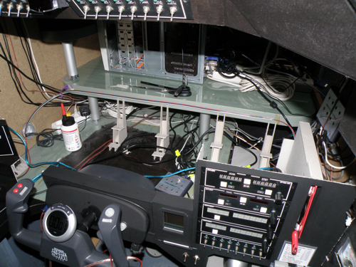
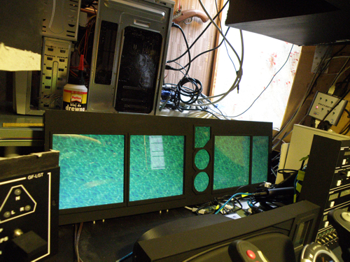
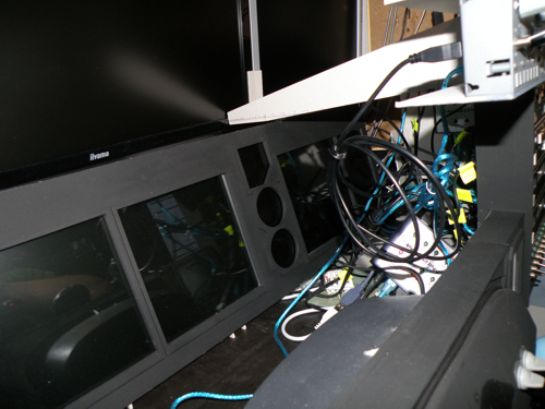
The front monitors were then enclosed with black card to close the gaps around the panel. Structural framing was added where needed, a new pilot ventilation duct was installed, and the wiring was bundled in preparation for the overhead panel.

Front monitors being enclosed Framed monitor installation Ventilation and cable preparation

Overhead panel

At the end of April 2007 I began the overhead. A support platform at the height of the main monitor formed the framework and also carried a ventilation duct. Because a single panel would have been impractical, the overhead was divided into five sections. The first carried two GoFlight modules; later sections included an illuminated keyboard, cabin lighting, master power, system power, ventilation controls, lighting switches and two starter controls.

First overhead-panel section Overhead support platform GoFlight modules in the overhead Illuminated keyboard overhead section Overhead lighting section Main overhead control section Overhead control panel before installation Overhead panel test

Once connected, the overhead supported three ventilation circuits with five fans and a dedicated 12 V lighting installation. TrackIR was moved between the GoFlight modules, improving its accuracy. After final testing, the overhead became the last major structural component of Version 1.

Completed and installed overhead TrackIR moved into the overhead Overhead panel from the pilot seat Completed overhead and lighting

Configuration and finishing work

By mid-2007 the equipment was fully configured. The MCP Pro had required two returns to GoFlight before the third unit worked correctly; installing it required part of the right wall to be dismantled and rewired. A dedicated map shelf was then added to the left wall for VATSIM flights, doubling as an armrest when hand-flying.

Fully configured first-version cockpit Cockpit controls after MCP installation Map shelf construction Map shelf installed on the left wall

In December 2007 the front section was finished: the ceiling and floor were completed, the throttle wall was sealed, and the seat platform was fixed permanently to the floor. Supports and wiring were covered, the interior was painted and the pedal-area cables were organized.

Finished front section of Version 1 Painted first-version interior Completed instrument panel Completed cockpit side wall First-version cockpit at night Interior finishing work Covered structural supports Pedal-area wiring after organization Finished floor and lower panel

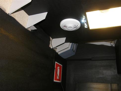
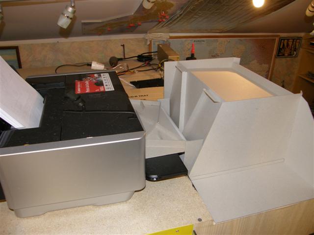
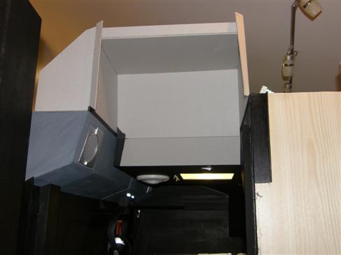
The final structural element was the roof section beside the entrance. It incorporated a slot connected to a printer, allowing charts and other documents to be delivered directly into the cockpit. Once the door and roof were sealed, the cabin remained completely dark even during the day.

Roof section by the cockpit door Printer paper slot in the overhead Sealed cockpit entrance

Version 1 completed

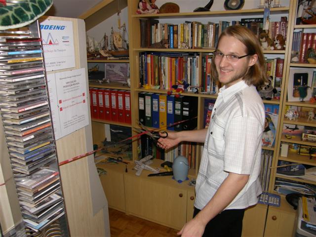
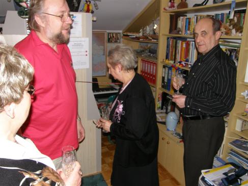
After more than two years of work, Version 1 was completed. A modest opening was held on 31 December 2007, when the main systems were demonstrated and invited pilots could try the cockpit. I would like to thank Andrzej Olejniczak and Edyta and Jacek Miazek, without whom completing the project would not have been possible.

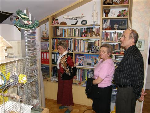
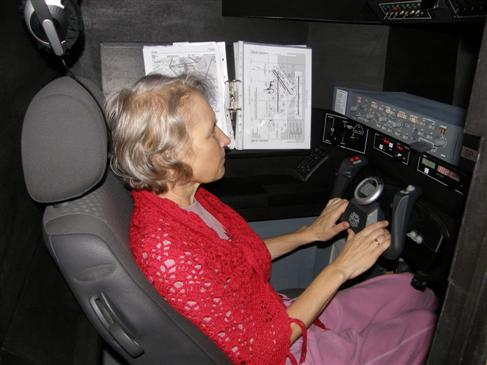
Version 1 opening event Guest flying Version 1 Cockpit demonstration Pilot at the completed cockpit Version 1 controls during the opening Home cockpit opening gathering Group photograph at the Version 1 opening
Back to top

Version 2: comprehensive rebuild

After a year of flying Version 1, the cockpit was rebuilt with a new visual system, instrument panel, radio stack, computers and network architecture.

October 2008 – January 2009

Climate control and touch-screen FMC

After a hot summer exposed the limitations of the original ventilation system, I installed an air-conditioning unit. The room could then be maintained at approximately 21°C, with the cockpit normally remaining below 23°C. This improved both pilot comfort and computer cooling.

I had long considered a dedicated hardware flight-management computer, but the cost and software integration were difficult to justify. A small touch-screen display designed for in-car entertainment offered a practical alternative. It operated as a standard monitor, allowed vasFMC controls to be pressed directly and was compact enough not to obstruct the entrance. It was installed beside the throttle, close to the location of an airliner CDU.

Air-conditioning system for the cockpit room Touch-screen FMC installation Touch-screen display beside the throttle

Demolition and ventilation upgrade

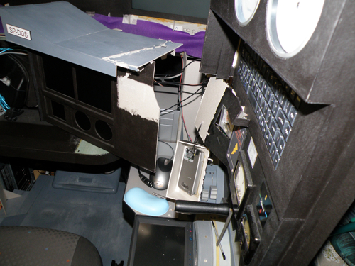
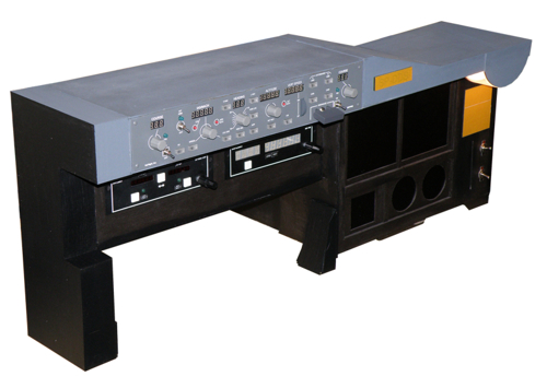
The Version 1 main panel had been built more permanently than expected, so removing it required substantial cutting. The centre and display modules were rebuilt outside the cockpit as a self-contained unit, fitted with additional lighting and switches, painted black and grey, and prepared for use with its monitor and software.

Version 1 panel during demolition Main panel removed from the cockpit Rebuilt self-contained Version 1 panel

The ventilation system was also renewed. Two fans exhausted warm air while four supplied cooler air. In a closed cockpit, the heat from computers and LCD monitors made planned airflow essential for component reliability and comfort during long flights.

Replacement cockpit ventilation fan

Radio stack

The new radio stack was made from 3 mm card and painted black. It carried two GF-46 modules, a GF-T8 and a GF-166, with provision for another GF-166. The stack was connected to a new seven-port USB hub and included switches for MCP lighting and panel backlighting, as well as a dedicated notepad area for copying clearances and oceanic position reports.

Radio-stack panel under construction Completed GoFlight radio stack Cabin cleaned and rewired for Version 2

New computer and network configuration

The original Flight Simulator computer was reassigned as a client machine behind the new displays. A more powerful PC was installed inside the cabin for FS2004.

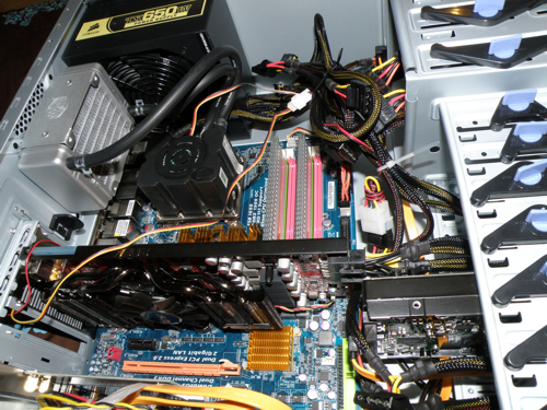
Processor
Intel Core 2 Duo E8600, 3.33 GHz, 1333 FSB, 6 MB cache
Graphics
ASUS EAH4870 DK Radeon HD4870, 1 GB GDDR5, 256-bit
Mainboard
Gigabyte GA-EP45T-DS3R
Memory
Corsair XMS3 DHX, 2 × 2 GB, 1600 MHz DDR3
Power supply
650 W

The configuration maintained the selected 25 FPS limit under demanding period conditions, including the installed add-ons and Ultimate Traffic at Chicago O'Hare.

New Flight Simulator computer

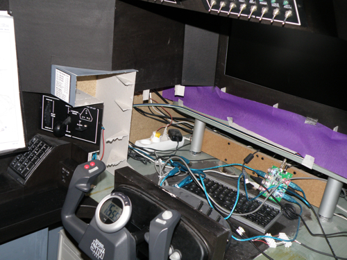
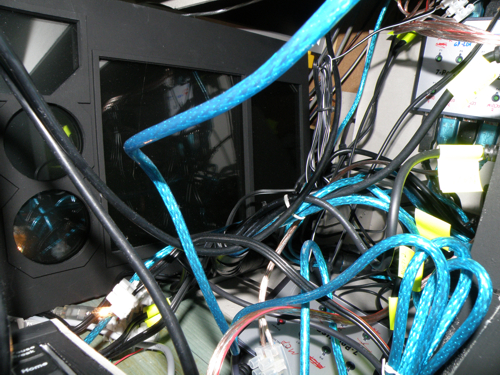
Networking the two computers was one of the most time-consuming parts of the rebuild. Stand-alone applications were moved to the client PC and automated with startup batch files. The simulator PC launched FS2004, the fuel planner, screenshot tool and FSUIPC; the client launched WideFS, vasFMC, FreeFD, Active Sky, GFKey, GFdisplay, pmSounds and FSInn. The result reduced preparation for an online flight to starting the two computers, completing the flight plan and connecting to VATSIM.

Dual-computer cockpit network

Main instrument panel

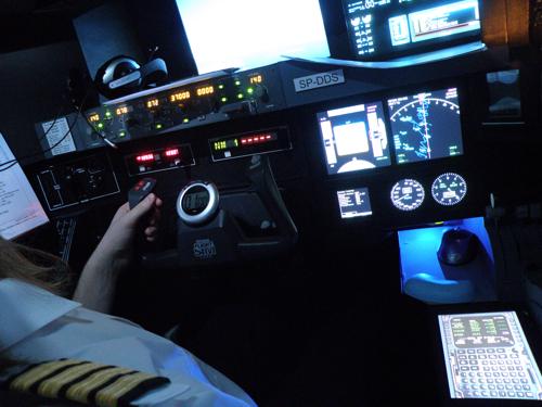
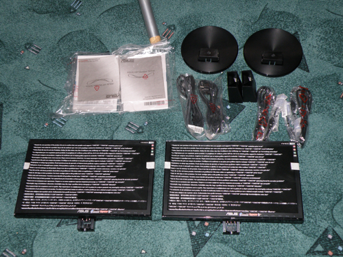
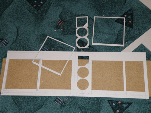
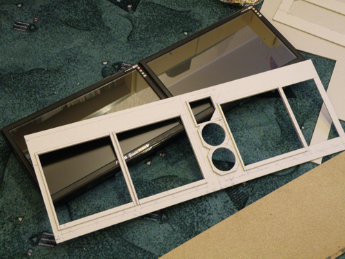
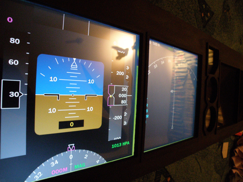
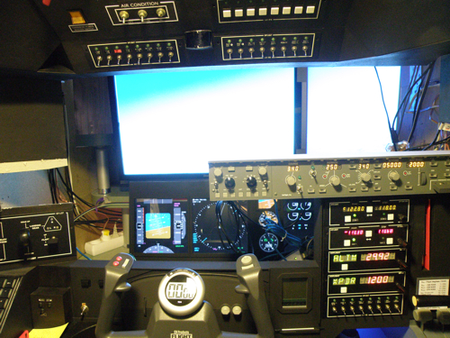
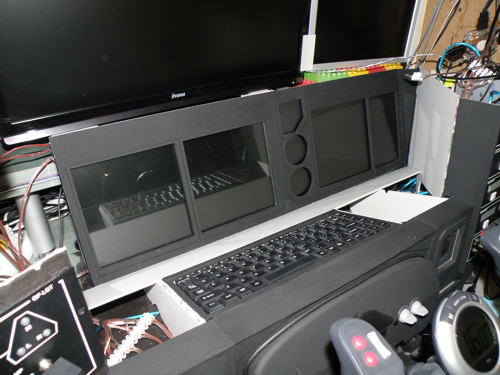
The new main panel used two layers of 3 mm card: a structural base and a top layer forming the display frames. Two 16-inch widescreen LCDs sat behind glass. vasFMC provided the primary displays and FreeFD the standby instruments, preserving basic information if one application failed. FSInn information occupied the far-right display area, visible when needed but outside the normal seated view.

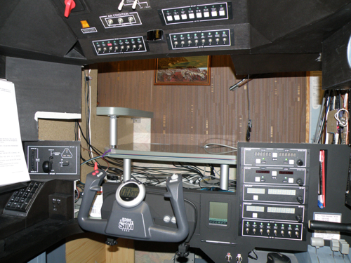
Version 2 panel base layer Version 2 display-frame layer Instrument-panel test fit Glass fitted ahead of the displays Display software during testing Standby flight display Main panel nearing completion Completed Version 2 instrument panel

Visual system

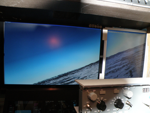
Guests repeatedly suggested a larger forward view. I eventually installed a 26-inch Iiyama monitor at 1900 × 1200 and paired it with a 20-inch monitor in portrait orientation. The resulting view was more than twice the previous size and created a much stronger sense of movement during turns, takeoffs, landings and taxiing. It also made visual approaches considerably easier.

Enlarged forward visual system

GoFlight modules

The final GoFlight installation distributed five panels to the client PC and the remainder to the simulator PC. Configuration used GFconfig, GFKey, GFdisplay, FSUIPC and WideFS.

  • GF-MCP Pro
  • GF-EFIS
  • GF-LGT
  • GF-46 × 2 (XPDR, altitude, ADF, DME)
  • GF-166 × 2 (COM1, COM2, NAV1, NAV2)
  • GF-P8
  • GF-T8 × 3 (lights, audio, fuel, power, de-ice)
Configured GoFlight avionics modules

Glareshield and windshield

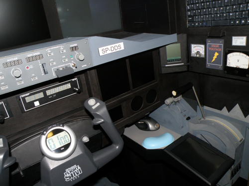
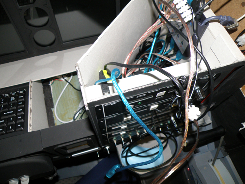
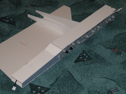
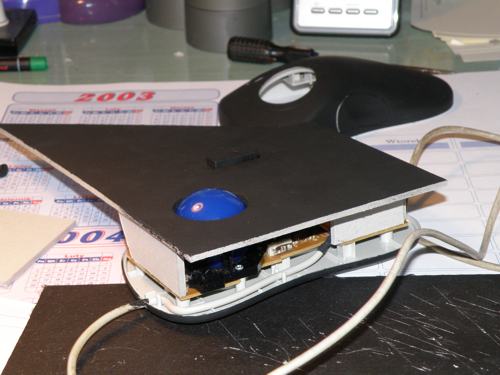
The glareshield required repeated measurement, test fitting and remaking of unsuitable parts. Its primary structure was formed from 3 mm card. A keyboard and trackball were installed behind the yoke to control the client computer, particularly for text communication during online flying.

Glareshield pattern and first pieces Glareshield structure under construction Glareshield test fitting Keyboard and trackball installation Glareshield surface finishing Completed glareshield

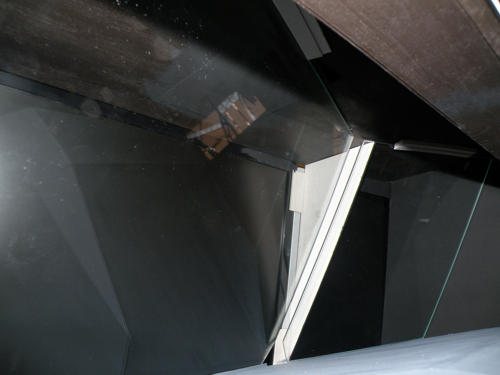
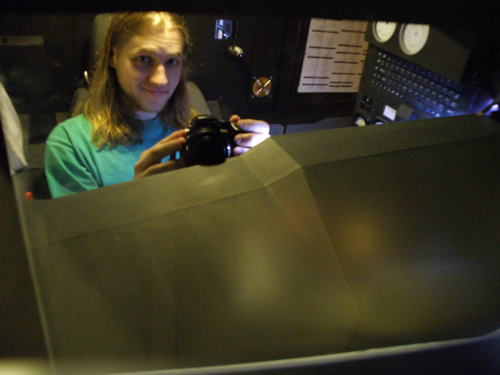
Two 5 mm glass windshield panels were cut to cardboard templates and retained between the glareshield and overhead without adhesive. The glass improved the enclosed flight-deck appearance and completed the visual separation between the cabin and the display system.

Windshield glass mounting detail Cockpit with fitted windshield

Version 2 completed

After final cosmetic work, the second version was completed on 17 January 2009, three and a half years after the project began. The rebuilt cockpit remained intact and operational until 2011.

Completed Version 2 home cockpit
Back to top

Continue through the archive

See the finished cockpit in the gallery and video, or review the preserved technical specification.